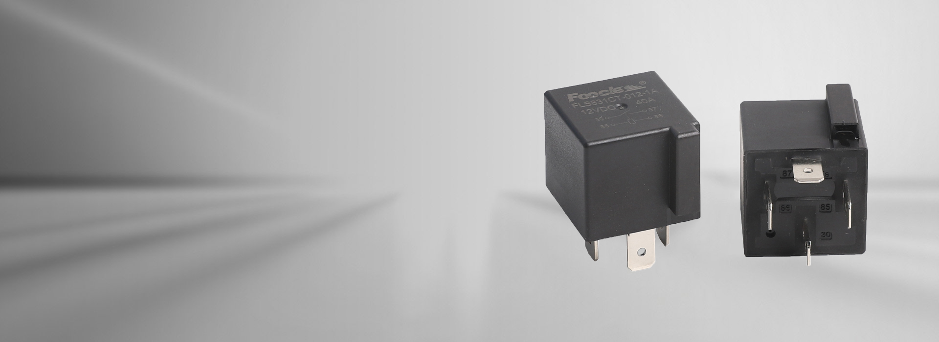
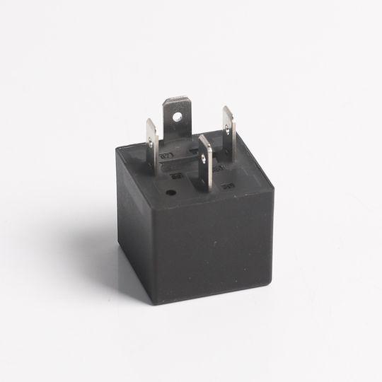
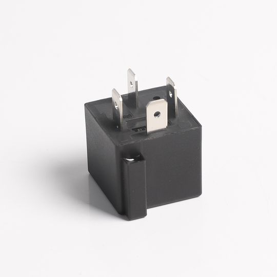
Internal Magnet Car Relay
Magnet-equipped model, strong magnetic arc quenching
40A switching capability, 12V/24V
It has 1A(NO-SPST), 1C(CO-SPDT) contact forms
Dust producted type and sealed type available
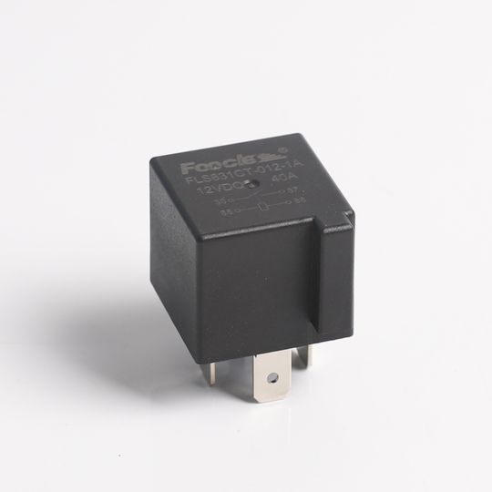
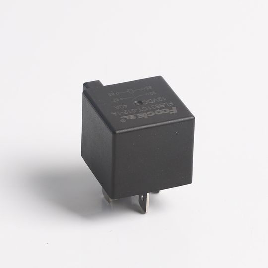
Outline dimensions: 26.3X26.3X23.3mm
Innovative Design to Meet Evolving Demands

These auto relays comply with international standards and can be easily inserted into sockets, where they remain securely in place.

We also use AgSno₂In contact material to further reduce arc erosion of the contacts and extend car relay’s service life.

We offer two contact configurations—normally open and changeover—to help you complete your project.

The housing is made of high-quality flame-retardant material, make it ideal for use in a variety of harsh environments without affecting car relay internals.
Long-lasting Car Relay
As a professional relay manufacturer in China, we have heard from an increasing number of distributors requesting a new series car relay that extends the service life of relays without significantly altering the product design. After extensive research and development by our engineers, we have finally designed a relay that uses magnets to extinguish arcs and protect the contacts. This does extend auto relay’s service life.
- Specification
- Coil Ratings
| Contact Form | 1A, 1C |
| Contact Material | AgSno2In |
| Max,Operating Current | 40A |
| Max.Operating Voltage | 27VDC |
| Rated Load(Resistive load) | 1A: 40A 13.5VDC 1C: NO/NC 40A/30A 13.5VDC |
| Insulation Resistance | 500VDC/100MΩ |
| Dielectric Strength(Coil and Contact) | 500VAC/M |
| Ambient Temperature | -40°C~+85°C |
| Operate/Release Time | ≤10ms |
| Release Time | ≤5ms |
| Mechanical Life | 1 X10⁶ |
| Electrical Life | 1 X10⁵ |
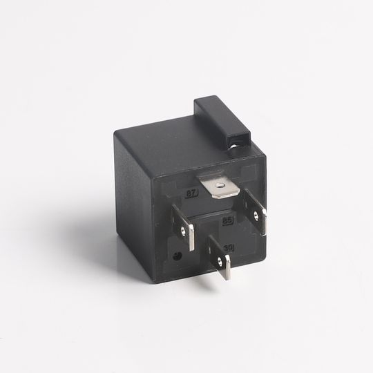
| Terminal Type | QC Terminal |
|
| Rated voltage (VDC) | Operate Voltage (VDC) | Release voltage (VDC) | Coil Resistance (Ω±10%) | Parallel Resistance (Ω±5%) | Equivalent Resistance (Ω±10%) | Coil Power (W) | Maximum coil voltage (VDC) | |
| 20 °C | 85°C | ||||||||
| Standard | 12 | ≤8.4 | ≥1.2 | 80 | – | – | 1.8 | 20.2 | 15.7 |
| 12 | ≤8.4 | ≥1.2 | 80 | 680 | 71.6 | 2.0 | 20.2 | 15.7 | |
| 24 | ≤16.8 | ≥2.4 | 320 | – | – | 1.8 | 40.5 | 31.5 | |
| 24 | ≤16.8 | ≥2.4 | 320 | 2700 | 286 | 2.0 | 40.5 | 31.5 | |
| l Low power | 12 | ≤8.4 | ≥1.2 | 90 | – | – | 1.6 | 20.2 | 15.7 |
| 12 | ≤8.4 | ≥1.2 | 90 | 680 | 79.5 | 1.8 | 20.2 | 15.7 | |
| 24 | ≤16.8 | ≥2.4 | 360 | – | – | 1.6 | 40.5 | 31.5 | |
| 24 | ≤16.8 | ≥2.4 | 360 | 2700 | 317.6 | 1.8 | 40.5 | 31.5 | |
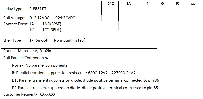
Ordering Guide
Outline Dimensions
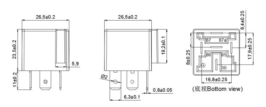
Remark: In case of no tolerance shown in outline dimension: outline dimension≤1mm, tolerance should be ±0.2mm;
Outline dimension>1mm and ≤5mm, tolerance should be ±0.3mm; outline dimension>5mm, tolerance should be ±0.4mm.
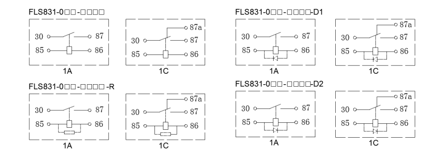
Wiring Diagram (Bottom View)
You can test it using the same methods you would use for a standard relay, such as measuring its resistance with a multimeter.
Because it isolates the control circuit from the load circuit, reducing the requirements for control switches and wiring harnesses and saving costs.
Yes, we offer both normally open and changeover types to help you implement different current logic.

